Beschreibung
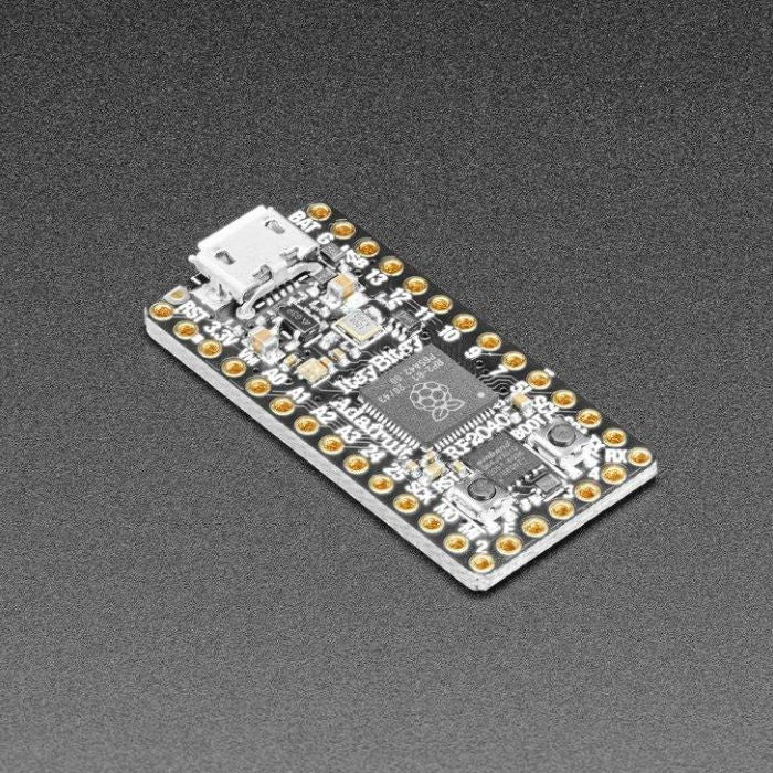
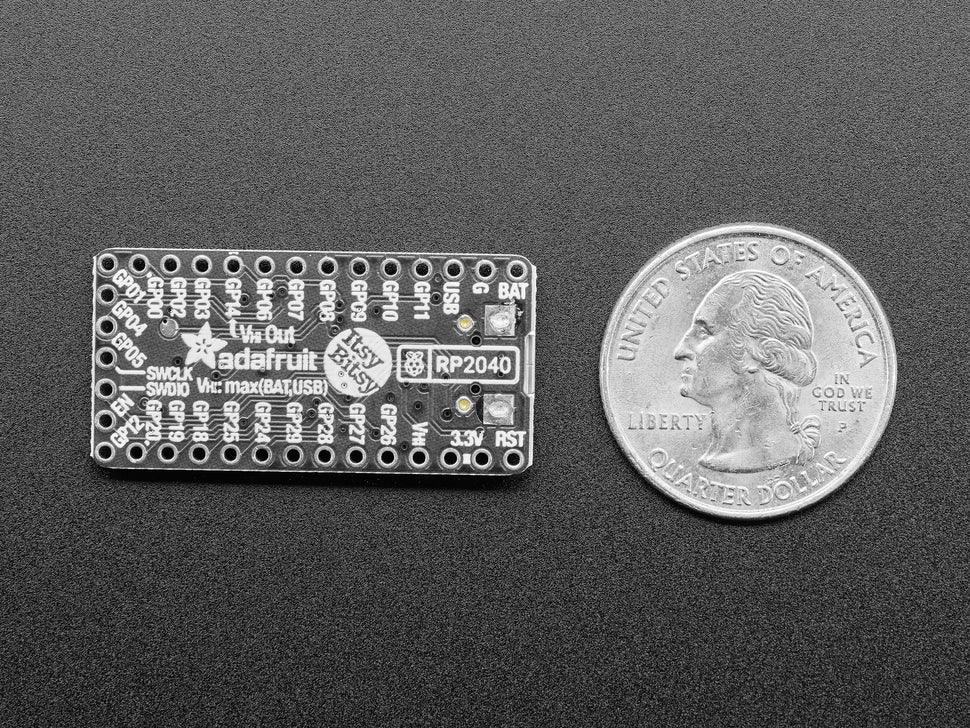
Ein neuer Chip bedeutet einen neuen ItsyBitsy, und der Raspberry Pi RP2040 ist da keine Ausnahme. Als wir diesen Chip sahen, dachten wir: "Dieser Chip wird großartig, wenn wir ihm die ItsyBitsy-Teensy-Weensy-Behandlung geben", und das haben wir getan! Dieser Itsy' verfügt über den RP2040 und alle Annehmlichkeiten, die Sie von der ItsyBitsy-Familie kennen und lieben
Was ist kleiner als ein Feather, aber größer als ein Trinket? Es ist ein Adafruit ItsyBitsy RP2040 mit dem Raspberry Pi RP2040! Klein, leistungsstark und mit einem ultraschnellen Dual-Cortex-M0+-Prozessor, der mit 125 MHz läuft - dieses Mikrocontroller-Board ist perfekt, wenn du etwas sehr Kompaktes mit viel Leistung und einer Menge Pins suchst. Dieses Itsy hat die Geschwindigkeit eines Sportwagens, aber die Geräumigkeit eines SUV mit 8 MB FLASH und 264KB SRAM.
Der ItsyBitsy RP2040 ist nur 1,4" lang und 0,7" breit, hat aber 6 Stromversorgungspins, 23 digitale GPIO-Pins (von denen 4 analoge Eingänge und 16 x PWM-Ausgänge sein können). Es ist der gleiche Chip wie der Feather RP2040 und der Raspberry Pi Pico, aber wirklich sehr klein. Er ist also ideal, wenn man einen Prototyp fertiggestellt hat und das Projekt viel kleiner machen möchte. Er verfügt sogar über 8 MB eingebauten SPI-Flash für Datenprotokollierung, Dateispeicherung oder CircuitPython/MicroPython-Code.
- Gleiche Größe und Formfaktor wie der Rest der ItsyBitsy-Familie und nahezu identische Pinbelegung
- Maße 1.4" x 0.7" x 0.2" (36mm x 18mm x 4mm) ohne eingelötete Header
- RP2040 32-Bit Cortex M0+ Dual-Core mit ~125 MHz bei 3,3 V Logik und Leistung
- 264 KB RAM
- 8 MB SPI FLASH Chip zum Speichern von Dateien und CircuitPython/MicroPython Code. Kein EEPROM
- Tonnenweise GPIO! 23 x GPIO-Pins mit den folgenden Fähigkeiten:
-Vier 12 Bit ADCs (einer mehr als beim Pico)
-Zwei I2C-, zwei SPI- und zwei UART-Peripherieanschlüsse, von denen wir einen für die "Haupt"-Schnittstelle an den Standardplätzen von ItsyBitsy beschriften
-16 x PWM-Ausgänge - für Servos, LEDs, etc.
-Die 10 digitalen 'Nicht-ADC/Nicht-Peripherie'-GPIO sind aufeinanderfolgend für maximale PIO-Kompatibilität
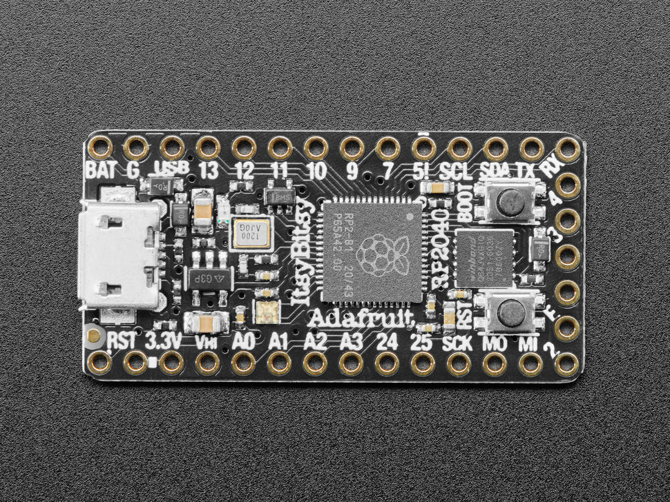
- Pin #11 rote LED für allgemeine Blinkzwecke
- RGB NeoPixel mit Stromversorgungs-Pin an GPIO, so dass Sie ihn für stromsparende Anwendungen entladen können.
- Sowohl Reset-Taste als auch Bootloader-Auswahltaste für schnelle Neustarts (kein Herausziehen und Wiedereinstecken, um den Code neu zu starten)
- 3,3-V-Regler mit 500-mA-Spitzenstromausgang
- 3,3-V-Stromversorgungs-/Einschaltstift
- Stromversorgung entweder über USB oder einen externen Ausgang (z.B. eine Batterie) - die Umschaltung erfolgt automatisch
- Ausgebrochene SWD-Pins für Debug-Zugriff
- 12-MHz-Quarz für perfektes Timing.
- Spezieller Vhigh-Ausgangspin liefert die höhere Spannung von VBAT oder VUSB zur Ansteuerung von NeoPixeln, Servos und anderen 5V-Logikgeräten. Digitaler 5-Pegel-verschobener Ausgang für Hochspannungs-Logikpegel-Ausgang.
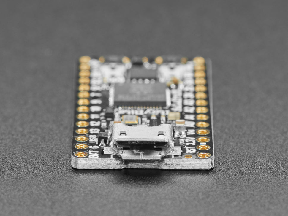
- Über den USB-Micro-B-Anschluss können Sie auf den integrierten ROM-USB-
Bootloader und das Debugging über die serielle Schnittstelle zugreifen.
Im RP2040 befindet sich ein permanenter ROM-USB-UF2-Bootloader. Das heißt, wenn Sie eine neue Firmware programmieren wollen, können Sie die BOOTSEL-Taste gedrückt halten, während Sie das Gerät an den USB-Anschluss anschließen (oder den RUN/Reset-Pin auf Masse ziehen), und es erscheint ein USB-Laufwerk, auf das Sie die Firmware ziehen können. Diejenigen, die Adafruit-Produkte verwendet haben, werden dies sehr vertraut finden - wir verwenden diese Technik auf allen unseren nativen USB-Boards. Beachten Sie nur, dass Sie nicht auf Reset doppelklicken, sondern BOOTSEL während des Bootens gedrückt halten, um den Bootloader zu starten!
Der RP2040 ist ein leistungsfähiger Chip, der die Taktrate unseres M4 (SAMD51) hat und zwei Kerne, die unserem M0 (SAMD21) entsprechen. Da es sich um einen M0-Chip handelt, verfügt er nicht über eine Fließkommaeinheit oder DSP-Hardwareunterstützung - wenn Sie also etwas mit umfangreichen Fließkommaberechnungen machen, wird dies in Software erledigt und ist daher nicht so schnell wie ein M4. Bei vielen anderen Rechenaufgaben erreichen Sie annähernd M4-Geschwindigkeiten!
Für die Peripherie gibt es zwei I2C-Controller, zwei SPI-Controller und zwei UARTs, die über GPIO gemultiplext sind - welche Pins auf welche Weise belegt werden können, ist in der Pinbelegung angegeben. Es gibt 16 PWM-Kanäle, jeder Pin hat einen Kanal, auf den er eingestellt werden kann (dito in der Pinbelegung).
Sie werden feststellen, dass es kein I2S-Peripheriegerät, kein SDIO und keine Kamera gibt, was ist damit? Nun, statt spezifischer Hardware-Unterstützung für serielle Peripheriegeräte wie diese, kommt das RP2040 mit dem PIO-State-Machine-System, das eine einzigartige und leistungsstarke Möglichkeit bietet, eigene Hardware-Logik und Datenverarbeitungsblöcke zu erstellen, die eigenständig laufen, ohne eine CPU zu beanspruchen. Zum Beispiel NeoPixels - oft bitbangen wir das Timing-spezifische Protokoll für diese LEDs. Für den RP2040 verwenden wir stattdessen ein PIO-Objekt, das den Datenpuffer einliest und den richtigen Bitstream mit perfekter Genauigkeit ausgibt. Dasselbe gilt für I2S-Audioeingänge und -ausgänge, LED-Matrix-Displays, 8-Bit- oder SPI-basierte TFTs und sogar VGA! In MicroPython und CircuitPython können Sie PIO-Steuerbefehle erstellen, um das Peripheriegerät zu skripten und es zur Laufzeit zu laden. Es gibt 2 PIO-Peripheriegeräte mit jeweils 4 Zustandsautomaten.
Zum Zeitpunkt der Markteinführung gibt es keine Arduino-Core-Unterstützung für dieses Board. Es gibt eine großartige C/C++-Unterstützung, eine offizielle MicroPython-Portierung und eine CircuitPython-Portierung! Wir empfehlen natürlich CircuitPython, weil wir denken, dass es der einfachste Weg ist, um anzufangen, und weil es die meisten unserer Treiber, Displays, Sensoren und mehr unterstützt, und zwar von Anfang an, so dass Sie unseren CircuitPython-Projekten und -Tutorials folgen können.
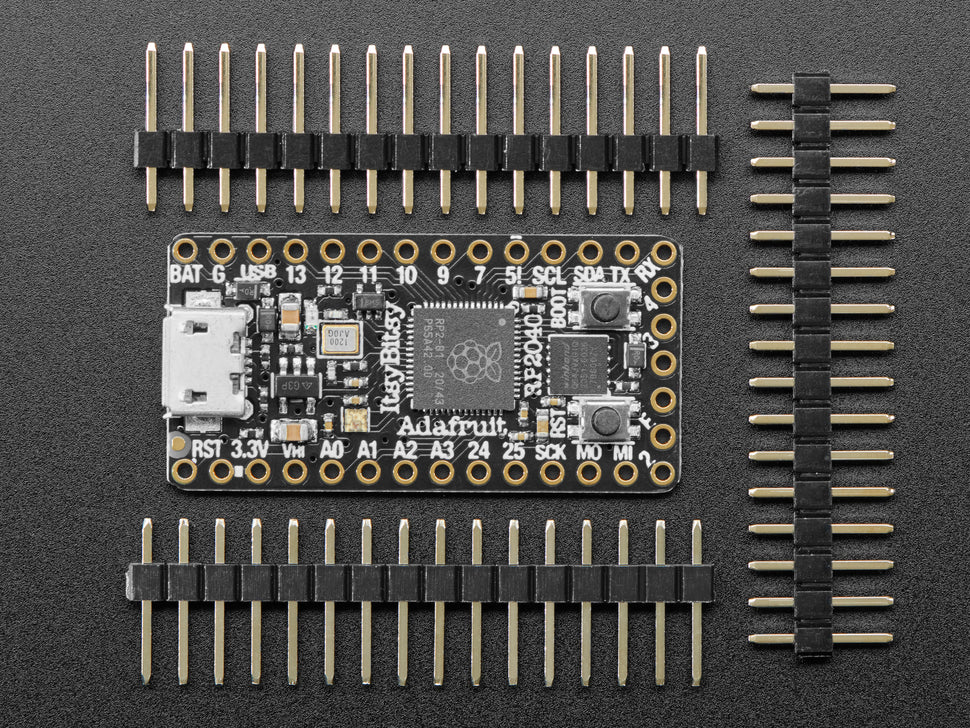
Dieser Itsy wird mit losen 0,1"-Leitungen geliefert, die Sie für die Verwendung auf einem Breadboard einlöten können!
Der RP2040 hat zwar viel Onboard-RAM (264KB), aber keinen eingebauten FLASH-Speicher. Dieser wird stattdessen von einem externen QSPI-Flash-Chip bereitgestellt. Auf diesem Board gibt es 8 MB, die zwischen dem laufenden Programm und dem von MicroPython oder CircuitPython verwendeten Dateispeicher aufgeteilt werden. Bei Verwendung von C/C++ steht der gesamte Flash-Speicher zur Verfügung, bei Verwendung von Python verbleiben etwa 7 MB für Code, Dateien, Bilder, Schriftarten usw.
Description
A new chip means a new ItsyBitsy, and the Raspberry Pi RP2040 is no exception. When we saw this chip, we thought, "This chip will be great if we give it the ItsyBitsy-Teensy-Weensy treatment," and we did! This 'Itsy' features the RP2040 and all the amenities you know and love from the ItsyBitsy family
What's smaller than a Feather, but bigger than a Trinket? It's an Adafruit ItsyBitsy RP2040 with the Raspberry Pi RP2040! Small, powerful, and with an ultra-fast dual cortex M0+ processor running at 125 MHz, this microcontroller board is perfect if you're looking for something very compact with a lot of power and a lot of pins. This Itsy has the speed of a sports car, but the roominess of an SUV with 8MB of FLASH and 264KB of SRAM.
The ItsyBitsy RP2040 is only 1.4" long and 0.7" wide, but has 6 power supply pins, 23 digital GPIO pins (of which 4 can be analog inputs and 16 x PWM outputs). It is the same chip as the Feather RP2040 and the Raspberry Pi Pico, but really very small. So it's ideal if you've finished a prototype and want to make the project much smaller. It even has 8 MB of built-in SPI flash for data logging, file storage, or CircuitPython/MicroPython code.
- Same size and form factor as the rest of the ItsyBitsy family and nearly identical pinout.
- Dimensions 1.4" x 0.7" x 0.2" (36mm x 18mm x 4mm) without soldered headers
- RP2040 32-bit Cortex M0+ dual core with ~125 MHz at 3.3 V logic and power
- 264 KB RAM
- 8 MB SPI FLASH chip for storing files and CircuitPython/MicroPython code. No EEPROM
- Tons of GPIO! 23 x GPIO pins with the following capabilities:
-Four 12 bit ADCs (one more than the Pico).
-Two I2C, two SPI and two UART peripheral ports, one of which we label for the "main" interface at the default ItsyBitsy locations.
-16 x PWM outputs - for servos, LEDs, etc.
-The 10 digital 'non-ADC/non-peripheral' GPIO are sequential for maximum PIO compatibility.
- Pin #11 red LED for general flashing purposes.
- RGB NeoPixel with power supply pin on GPIO so you can discharge it for low power applications.
- Both reset button and bootloader selection button for quick reboots (no unplugging and re-plugging to restart code)
- 3.3 V regulator with 500 mA peak current output
- 3.3-V power supply/power-on pin
- Powered either by USB or an external output (e.g., a battery) - switching is automatic
- Broken SWD pins for debug access
- 12 MHz crystal for perfect timing.
- Special Vhigh output pin provides the higher voltage of VBAT or VUSB for driving NeoPixels, servos and other 5V logic devices. Digital 5-level shifted output for high voltage logic level output.
- USB Micro-B port provides access to the integrated ROM USB-
Bootloader and serial port debugging can be accessed.
There is a permanent ROM-USB-UF2 bootloader in the RP2040. This means that if you want to program new firmware, you can hold down the BOOTSEL button while connecting the device to the USB port (or pulling the RUN/Reset pin to ground), and a USB drive will appear to which you can pull the firmware. Those who have used Adafruit products will find this very familiar - we use this technique on all of our native USB boards. Just note that you don't double-click reset, but hold down BOOTSEL while booting to start the bootloader!
The RP2040 is a powerful chip that has the clock speed of our M4 (SAMD51) and two cores equivalent to our M0 (SAMD21). Since it's an M0 chip, it doesn't have a floating point unit or DSP hardware support - so if you're doing anything with extensive floating point calculations, it's done in software and therefore isn't as fast as an M4. For many other computing tasks, you'll get close to M4 speeds!
For peripherals, there are two I2C controllers, two SPI controllers, and two UARTs multiplexed via GPIO - see the pinout for which pins can be assigned which way. There are 16 PWM channels, each pin has a channel it can be set to (ditto in the pinout).
You will notice that there is no I2S peripheral, no SDIO and no camera, what about that? Well, instead of specific hardware support for serial peripherals like these, the RP2040 comes with the PIO state machine system, which provides a unique and powerful way to create your own hardware logic and data processing blocks that run independently without taking up a CPU. For example, NeoPixels - we often bitbang the timing-specific protocol for these LEDs. For the RP2040, we instead use a PIO object that reads the data buffer and outputs the correct bitstream with perfect accuracy. The same is true for I2S audio inputs and outputs, LED matrix displays, 8-bit or SPI-based TFTs, and even VGA! In MicroPython and CircuitPython, you can create PIO control commands to script the peripheral and load it at runtime. There are 2 PIO peripherals with 4 state machines each.
At launch, there is no Arduino core support for this board. There is great C/C++ support, an official MicroPython port, and a CircuitPython port! We recommend CircuitPython, of course, because we think it's the easiest way to get started, and because it supports most of our drivers, displays, sensors, and more, right from the start, so you can follow along with our CircuitPython projects and tutorials.
This Itsy comes with loose 0.1" leads that you can solder in for use on a breadboard!
The RP2040 has plenty of onboard RAM (264KB), but no built-in FLASH memory. This is instead provided by an external QSPI flash chip. There are 8MB on this board, which is shared between the running program and the file memory used by MicroPython or CircuitPython. When using C/C++, the entire flash memory is available, when using Python, about 7 MB remain for code, files, images, fonts, etc.
Sicherheitsangaben
- Lesen Sie die Bedienungsanleitung sorgfältig durch, bevor Sie das Produkt verwenden.
- Stellen Sie sicher, dass alle Montage- und Installationsanweisungen des Herstellers sorgfältig befolgt werden.
- Verwenden Sie das Produkt nur für den vorgesehenen Zweck.
- Die unsachgemäße Nutzung dieses Produkts kann zu schweren Verletzungen oder Sachschäden führen.
- Nicht für Kinder unter 10 Jahren geeignet.
- Bei unsachgemäßer Verwendung besteht eine Verletzungsgefahr.
- Dieses Produkt entspricht den geltenden Sicherheitsanforderungen der Europäischen Union.
- Dieses Produkt wurde gemäß der GPSR geprüft, die sicherstellt, dass alle relevanten Sicherheitsanforderungen für Konsumgüter eingehalten werden.
Nachverfolgbarkeitsinformationen
Jedes Produkt verfügt über eines oder mehrere der folgenden Merkmale:
- Ein CE-Kennzeichen, das die Einhaltung der Sicherheits-, Gesundheits- und Umweltschutzanforderungen der Europäischen Union anzeigt.
- Eine eindeutige Serien- oder Chargennummer, um die Nachverfolgbarkeit zu gewährleisten und bei Bedarf Rückrufaktionen zu unterstützen.
- Hersteller- und Importeurangaben für den Kundensupport und Sicherheitsanfragen.
Überwachung und Berichterstattung von Vorfällen
Für den unwahrscheinlichen Fall eines Produktproblems haben wir Verfahren implementiert, um:
- Kundenbeschwerden zeitnah bearbeiten.
- Schwerwiegende Vorfälle über das EU Safety Gate/RAPEX-System melden.
- Mit den Marktüberwachungsbehörden zusammenarbeiten, um die öffentliche Sicherheit zu gewährleisten.
Kontakt:
- Email: support [@] pi3g.com
- Telefon: 0341 / 392 858 40
Dieses Produkt ist vollständig mit allen geltenden EU-Vorschriften konform, um die Sicherheit unserer geschätzten Kunden zu gewährleisten.

