Dieser Artikel ist EOL. Das neue CANPico v2 with Pico WH Pre-installed haben wir bereits im Shop.
CAN-Bus ist ein Protokoll, das in Hunderten von Millionen von Geräten verwendet wird, darunter Autos, LKWs, Busse, Baumaschinen, Schiffe, Traktoren und Raumfahrzeuge (es gibt sogar einen CAN-Bus, der den Mars umkreist). Das Canis Labs CANPico ist eine Trägerplatine im 'Socken'-Format für einen Rapsberry Pi Pico: einfach auf den Pico löten und schon ist er mit einem fortschrittlichen CAN-Controller und Transceiver verbunden, bereit für den Anschluss an CAN-Bus-Leitungen über eine einfache Schraubklemme. Der CANPico enthält einen Instrumenten-Header mit den analogen CAN H- und CAN L-Signalen sowie den digitalen RX- und TX-Signalen für die Verwendung mit einem Oszilloskop oder Logikanalysator. Die Softwareunterstützung erfolgt über ein quelloffenes MicroPython SDK.
Im Lieferumfang sind Pico und MicroPython vorinstalliert.
Das quelloffene MicroPython-SDK von Canis Labs bietet eine ausgefeilte CAN-API, einschließlich prioritätsinversionsfreier Treiber, Zeitstempel mit 1μs-Genauigkeit, große Puffer und eine API zur Triggerung eines Logikanalysators oder Oszilloskops. Außerdem gibt es Unterstützung für die Kommunikation mit einem Host-Gerät über USB (über das MIN-Protokoll), um Anwendungen wie Bus-Logging oder sogar die Verwendung eines CANPico als PC-CAN-Schnittstelle zu ermöglichen. Das SDK enthält auch das CANHack-Toolkit für Low-Level-Fehlerinjektion. Das SDK ermöglicht die Ausführung von Python-Code auf dem Dual-Core RP2040-Mikrocontroller des Raspberry Pi Pico und reagiert in Echtzeit auf den CAN-Verkehr mit Zeiten, die in Mikrosekunden statt Millisekunden gemessen werden, was ihn zu einer hervorragenden Plattform für Hardware-in-the-Loop-Tests und Emulationen macht.
Hauptmerkmale der Hardware
- Microchip MCP2517/18FD CAN-Controller mit 2Kbyte Pufferspeicher
- Microchip MCP2562FD CAN-Transceiver
- Schraubklemme für direkten Zugang zur CAN-High/Low-Twisted-Pair-Verdrahtung und einem gemeinsamen Massebezug
- Steckbrücke für einen standardmäßigen 120Ω-CAN-Busabschlusswiderstand
- Jumper zum Aktivieren und Deaktivieren des Sendeeingangs für den Transceiver
Schnittstellen
- Header-Pins für den Zugriff des Logikanalysators auf die digitalen CAN-Signale (TX- und RX-Pins des Transceivers)
- Stiftleiste für den Zugriff des Oszilloskops auf die analogen CAN-Signale (CAN High/Low, Masse)
- TRIG-Pin für Logikanalysator- und Oszilloskop-Triggerung auf programmierbare CAN-Ereignisse
- Direkter GPIO-Zugriff auf CAN RX- und TX-Pins zur Software-Fehlerinjektion
- GPIO-Steuerung über Transceiver im Low-Power-Standby
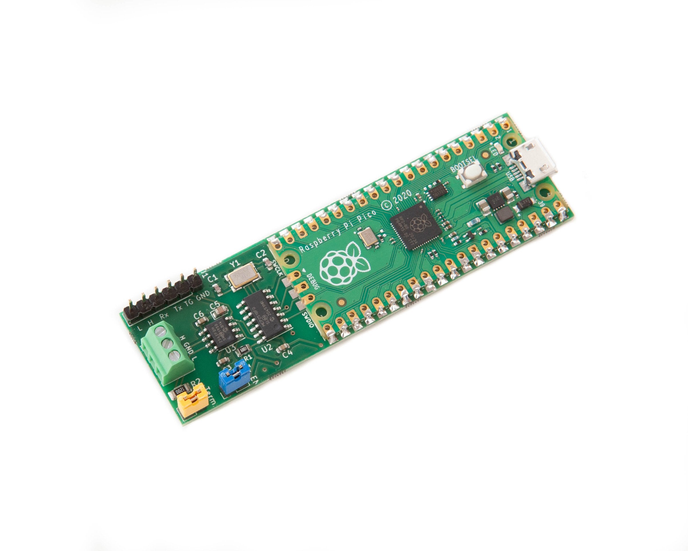
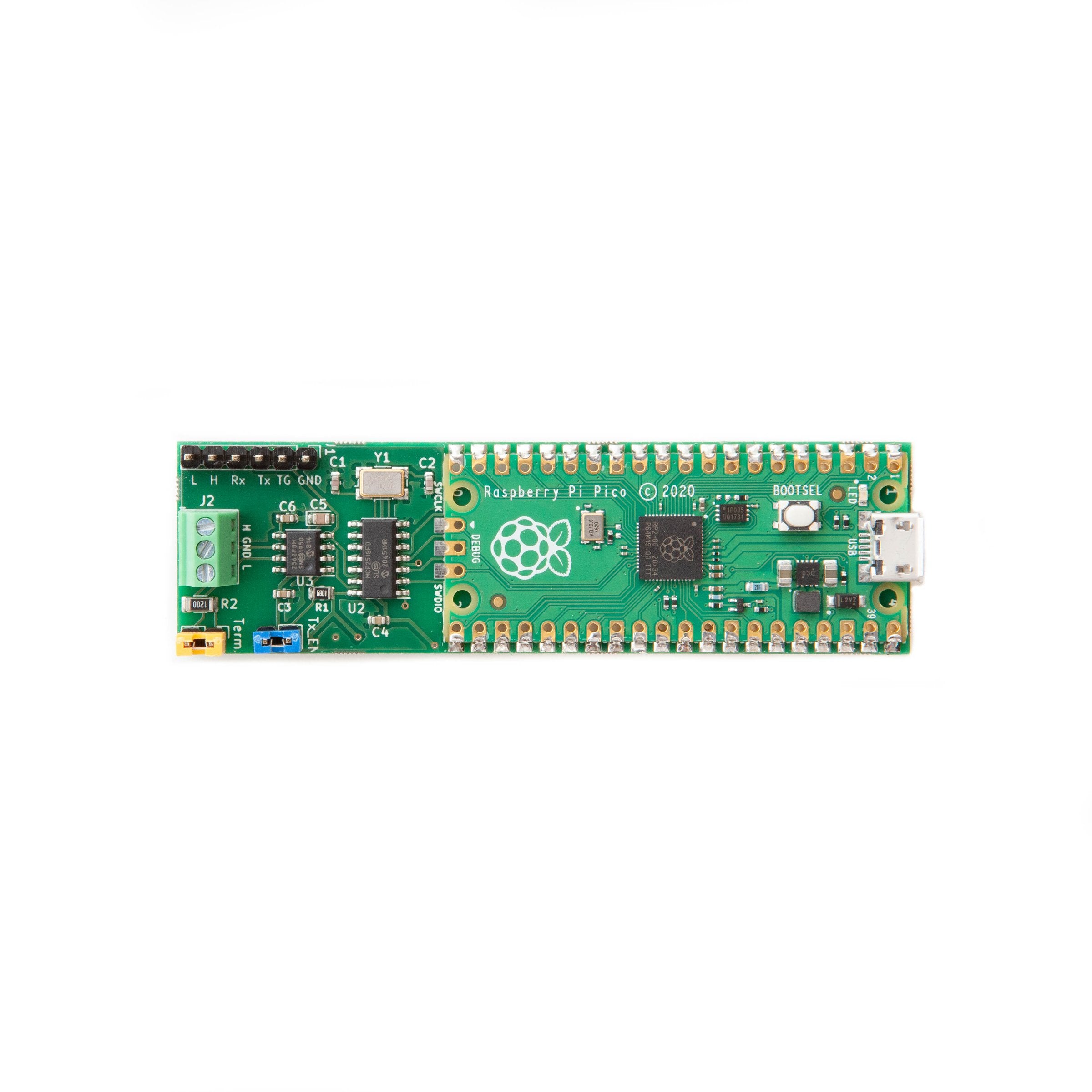
Der Raspberry Pi Pico ist so konzipiert, dass er mit Hilfe der "Halbmond"-Kanten auf ein Board gelötet werden kann, so dass die Header-Pins frei bleiben. Die anderen Anschlüsse sind USB (für Stromversorgung und Verbindung zu einem Host) und der CAN-Bus. Die 6-polige Stiftleiste ist für einen Logik-Analysator und ein Oszilloskop vorgesehen, um CAN-Rohsignale zu sehen, der gelbe Jumper dient zum Aktivieren des Abschlusswiderstandes, und der blaue Jumper aktiviert die Übertragung auf dem Bus (wenn dieser entfernt wird, ist das Board darauf beschränkt, nur den CAN-Bus abzuhören, eine nützliche Sicherheitsfunktion).
Software-Unterstützung
Die Softwareunterstützung erfolgt mit einem MicroPython SDK, das die folgenden APIs besitzt:
- CAN-API
- CANHack-Toolkit-API
- Trigger API zum Triggern von Testgeräten bei CAN-Fehlern und CAN-Frames mit einer bestimmten ID und Nutzlast
- MIN-API zur Kommunikation mit einem Host-PC über eine zweite virtuelle serielle USB-Schnittstelle
Die CAN-API besteht aus den folgenden Python-Klassen:
- Die CAN-Klasse stellt die Steuerung und den Status des CAN-Controllers zur Verfügung
- Die Klasse CANFrame kapselt CAN-Frames, die entweder in Software erzeugt oder von der Hardware des CAN-Controllers empfangen werden
- Die Klasse CANError kapselt CAN-Fehler-Frames, die durch den Empfang von der CAN-Controller-Hardware erzeugt werden
- Die Klasse CANID beschreibt eine CAN-ID: jeder CAN-Frame hat eine CAN-ID, aber viele Frames können die gleiche ID haben
- Die CANIDFilter-Klasse beschreibt, wie ein CAN-Controller CAN-Frames anhand ihrer CAN-ID identifizieren und akzeptieren soll
Die MIN-API bietet MIN-Protokollunterstützung für eine zuverlässige Kommunikation mit einem Host-PC. Einige der CAN-API-Aufrufe verwenden eine binäre Darstellung, damit Elemente über MIN übertragen werden können.
Ressourcen
- Das Hardware-Referenzhandbuch (PDF) für das CANPico Board (Version 01, Ausgabedatum 2021-04-29, 8 Seiten) inklusive Schaltplan.
- Das MicroPython SDK Referenzhandbuch (PDF) für das CANPico Board (Version 01, Ausgabedatum 2021-04-29, 32 Seiten). Dokumentiert sowohl die MicroPython CAN API als auch die CANHack API.
- Die aktuelle Firmware (.uf2, Ausgabedatum 2021-05-10). Basiert auf dem v1.15 Release von MicroPython für den Pico. Der Quellcode ist als Patch-Datei für diese MicroPython-Version freigegeben (siehe README.txt für Details).
- Die aktuellen Schaltpläne (PDF) und das Kicad-Design (.kicad_pcb) für das CANPico-Board.
- Die canpico.py Beispiele für das CANPico Board (die Thonny IDE kann verwendet werden, um die Datei auf das Pico Dateisystem zu legen)
- Es gibt einen Blog-Beitrag, der CANHack vorstellt und ein Demonstrationsvideo (Beachten Sie, dass beide die CANHack MicroPython API verwenden, aber auf dem STM32-basierten PyBoard und nicht auf dem Raspberry Pi Pico).
English description
CAN bus is a protocol used in hundreds of millions of devices including cars, trucks, buses, construction machines, ships, tractors, and spacecraft (there is even a CAN bus orbiting Mars). The Canis Labs CANPico a carrier board in a ‘sock’ format for a Rapsberry Pi Pico: simply solder on the Pico and it is connected to an advanced CAN controller and transceiver, ready for connection to CAN bus wires via a simple screw terminal. The CANPico includes an instrument header with the analog CAN H and CAN L signals and the digital RX and TX signals for use with an oscilloscope or logic analyzer. Software support is via an open source MicroPython SDK.
Shipped with Pico and MicroPython pre-installed.
The open source MicroPython SDK from Canis Labs provides a sophisticated CAN API, including priority-inversion free drivers, 1μs accuracy timestamps, large buffers and an API for triggering a logic analyzer or oscilloscope. And there is support for communicating to a host device over USB (via the MIN protocol) to enable applications like bus logging or even using a CANPico as a PC CAN interface. The SDK also includes the CANHack toolkit for low-level error injection. The SDK lets Python code run on the dual-core RP2040 microcontroller of the Raspberry Pi Pico and respond in real-time to CAN traffic with times measured in microseconds rather than milliseconds, making it a great platform for hardware-in-the-loop test and emulation.
Main hardware features
- Microchip MCP2517/18FD CAN controller with 2Kbyte buffer space
- Microchip MCP2562FD CAN transceiver
- Screw terminal for direct access to CAN High/Low twisted pair wiring and a common ground reference
- Jumper for a standard 120Ω CAN bus termination resistor
- Jumper for enabling and disabling transmit input to the transceiver
Interfacing
- Header pins for logic analyzer access to digital CAN signals (TX and RX pins of the transceiver)
- Header pins for oscilloscope access to the analog CAN signals (CAN High/Low, ground)
- TRIG pin for logic analyzer and oscilloscope triggering on programmable CAN events
- Direct GPIO access to CAN RX and TX pins for software error injection
- GPIO control over transceiver low power standby
The Raspberry Pi Pico is designed to be soldered on to a board using the ‘half moon’ edges, leaving header pins free. The other connections are USB (for power and connectivity to a host) and the CAN bus. The 6-pin header is intended for a logic analyzer and oscilloscope to see raw CAN signals, the yellow jumper is for enabling the termination resistor, and the blue jumper enables transmission on the bus (if this is removed then the board is restricted to only listening to the CAN bus, a useful security feature).
Software support
The software support is provided with a MicroPython SDK that has the following APIs:
- CAN API
- CANHack toolkit API
- Trigger API for triggering test instruments on CAN errors and CAN frames with a specified ID and payload
- MIN API to communicate with a host PC over a second virtual USB serial port
The CAN API consists of the following Python classes:
- The CAN class provides control and status of the CAN controller
- The CANFrame class encapsulates CAN frames, which are either created in software or by receiving them from the CAN controller hardware
- The CANError class encapsulates CAN error frames, which are created receiving them from the CAN controller hardware
- The CANID class describes a CAN ID: every CAN frame has a CAN ID, but many frames can have the same ID
- The CANIDFilter class describes how a CAN controller should identify and accept CAN frames based on their CAN ID
The MIN API provides MIN protocol support for reliable communication with a host PC. Some of the CAN API calls use a binary representation to allow items to be carried over MIN.
Resources
- The Hardware Reference Manual (PDF) for the CANPico board (version 01, issue date 2021-04-29, 8 pages) including schematics.
- The MicroPython SDK Reference Manual (PDF) for the CANPico board (version 01, issue date 2021-04-29, 32 pages). Documents both the MicroPython CAN API and CANHack API.
- The latest firmware (.uf2, release date 2021-05-10). Based on the v1.15 release of MicroPython for the Pico. The source code is released as a patch file for this MicroPython version (see README.txt for details).
- The latest schematics (PDF) and Kicad design (.kicad_pcb) for the CANPico board.
- The canpico.py examples for the CANPico board (the Thonny IDE can be used to put the file on to the Pico file system)
- There is a blog post introducing CANHack and a demonstration video (Note that these both use the CANHack MicroPython API but on the STM32-based PyBoard rather than the Raspberry Pi Pico).
Sicherheitsangaben
- Lesen Sie die Bedienungsanleitung sorgfältig durch, bevor Sie das Produkt verwenden.
- Stellen Sie sicher, dass alle Montage- und Installationsanweisungen des Herstellers sorgfältig befolgt werden.
- Verwenden Sie das Produkt nur für den vorgesehenen Zweck.
- Die unsachgemäße Nutzung dieses Produkts kann zu schweren Verletzungen oder Sachschäden führen.
- Nicht für Kinder unter 10 Jahren geeignet.
- Bei unsachgemäßer Verwendung besteht eine Verletzungsgefahr.
- Dieses Produkt entspricht den geltenden Sicherheitsanforderungen der Europäischen Union.
- Dieses Produkt wurde gemäß der GPSR geprüft, die sicherstellt, dass alle relevanten Sicherheitsanforderungen für Konsumgüter eingehalten werden.
Nachverfolgbarkeitsinformationen
Jedes Produkt verfügt über eines oder mehrere der folgenden Merkmale:
- Ein CE-Kennzeichen, das die Einhaltung der Sicherheits-, Gesundheits- und Umweltschutzanforderungen der Europäischen Union anzeigt.
- Eine eindeutige Serien- oder Chargennummer, um die Nachverfolgbarkeit zu gewährleisten und bei Bedarf Rückrufaktionen zu unterstützen.
- Hersteller- und Importeurangaben für den Kundensupport und Sicherheitsanfragen.
Überwachung und Berichterstattung von Vorfällen
Für den unwahrscheinlichen Fall eines Produktproblems haben wir Verfahren implementiert, um:
- Kundenbeschwerden zeitnah bearbeiten.
- Schwerwiegende Vorfälle über das EU Safety Gate/RAPEX-System melden.
- Mit den Marktüberwachungsbehörden zusammenarbeiten, um die öffentliche Sicherheit zu gewährleisten.
Kontakt:
- Email: support [@] pi3g.com
- Telefon: 0341 / 392 858 40
Dieses Produkt ist vollständig mit allen geltenden EU-Vorschriften konform, um die Sicherheit unserer geschätzten Kunden zu gewährleisten.


