


Adafruit Medium 16x32 RGB LED matrix panel - 6mm Pitch
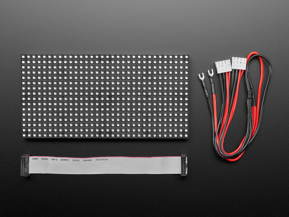
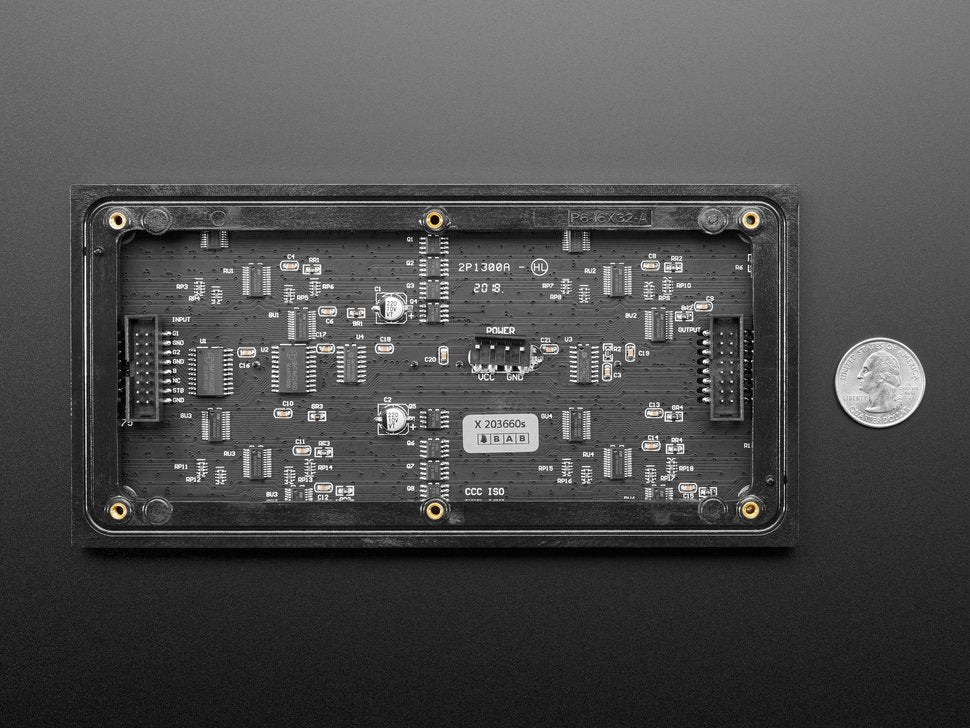
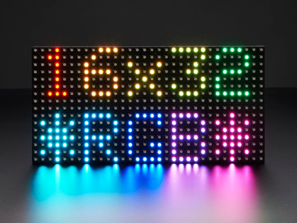
Holen Sie sich mit diesem 16 x 32 RGB-LED-Matrix-Panel ein bisschen Times Square in Ihr Zuhause. Diese Panels werden normalerweise verwendet, um Videowände zu machen, in New York sehen wir sie an den Seiten von Bussen und Bushaltestellen, um Animationen oder kurze Videoclips anzuzeigen. Adafruit fanden, dass sie wirklich cool aussahen, also haben wir ein paar Kisten davon bei einer Fabrik abgeholt. Sie haben 512 helle RGB-LEDs, die in einem 16x32-Raster auf der Vorderseite angeordnet sind. Auf der Rückseite befindet sich eine Platine mit zwei IDC-Anschlüssen (ein Eingang, ein Ausgang: theoretisch kann man diese miteinander verketten) und 12 16-Bit-Latches, mit denen man das Display mit einer Abtastrate von 1:8 ansteuern kann.
Diese Displays sind "verkettbar" - verbinden Sie einen Ausgang mit dem nächsten Eingang - aber unser Arduino-Beispielcode unterstützt dies (noch) nicht. Es erfordert einen Hochgeschwindigkeitsprozessor und mehr RAM als der Arduino hat!
Diese Panels benötigen 12 digitale Pins (6 Bit Daten, 6 Bit Steuerung) und eine gute 5V-Versorgung, bis zu 2A pro Panel. Wir empfehlen unseren 2A geregelten 5V-Adapter und dann das Anlöten einer Buchse, z.B. von unserem Verlängerungskabel. Bitte schauen Sie sich unser Tutorial für weitere Details an!
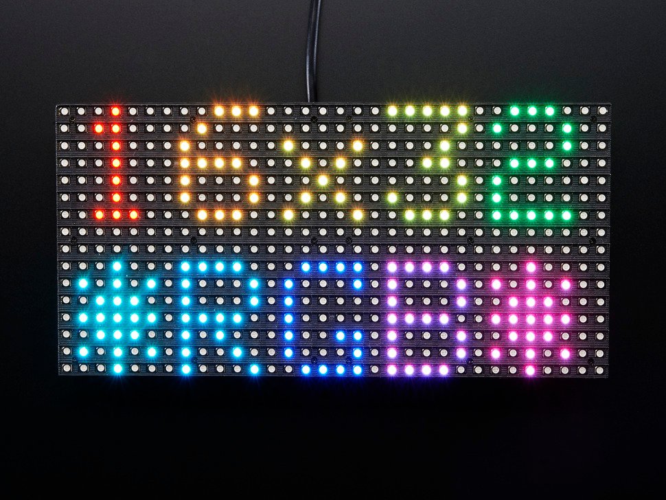
Beachten Sie, dass diese Displays für die Ansteuerung durch FPGAs oder andere Hochgeschwindigkeits-Prozessoren ausgelegt sind: Sie haben keinerlei eingebaute PWM-Steuerung. Stattdessen müssen Sie den Bildschirm immer wieder neu zeichnen, um das Ganze "manuell" zu PWMen. Auf einem 16-MHz-Arduino haben wir es geschafft, 12-Bit-Farben (4096 Farben) mit 20% CPU-Auslastung zu erzeugen, aber dieses Display würde wirklich glänzen, wenn es von einem FPGA, CPLD, Propeller, XMOS oder einem anderen Hochgeschwindigkeits-Multicore-Controller angesteuert würde. Die gute Nachricht ist, dass das Display vor-weiß-balanciert ist mit schöner Gleichmäßigkeit, so dass, wenn Sie alle LEDs einschalten, es nicht ein besonders getöntes Weiß ist.
Natürlich würden wir Sie nicht mit einem Datenblatt und einem "Viel Glück!" zurücklassen. Wir haben einen vollständigen Schaltplan und einen funktionierenden Code für die Arduino-Bibliothek mit Beispielen für das Zeichnen von Pixeln, Linien, Rechtecken, Kreisen und Text. Sie werden Ihre Farbe innerhalb einer Stunde zum Strahlen bringen! Auf einem Arduino benötigen Sie 12 digitale Pins und etwa 800 Byte RAM, um das 12-Bit-Farbbild zu puffern. Zur Zeit haben wir keine Verdrahtungsdokumentation für den MEGA, aber wir werden unser Tutorial in der nächsten Woche aktualisieren, um den MEGA hinzuzufügen
Bitte beachten Sie! Bei diesen Panels handelt es sich um Restposten aus Fabriken, die riesige Leuchtplatten herstellen. Aus diesem Grund können das Aussehen, die LED-Tönung, der Stil und die Länge des Stromkabels sowie die genaue Größe von Charge zu Charge variieren, auch wenn die grundlegende Bedienung, die Codebasis und das Tutorial gleich sind.
TECHNISCHE DETAILS
- Datenblatt
- Abmessungen: 192mm x 96mm x 12mm (7.6" x 3.8" x 0.5")
- Gewicht des Panels mit IDC-Kabel und Netzkabel: 170g
- 5V geregelter Stromeingang, 2,5A max (alle LEDs an)
- 5V Datenlogikpegeleingang
- ~2000 mcd LEDs auf 6mm Raster
- Kompatibel mit M3-Montageschrauben
- 1/8 Abtastrate
- Anzeige im Innenbereich, 140 Grad Sichtbarkeit
- Displays sind 'verkettbar' - verbinden Sie einen Ausgang mit dem nächsten Eingang - aber unser Arduino-Beispielcode unterstützt dies noch nicht
Adafruit Medium 16x32 RGB LED matrix panel - 6mm Pitch
Bring a little Times Square into your home with this 16 x 32 RGB LED matrix panel. These panels are usually used to make video walls, in New York we see them on the sides of buses and bus stops to display animations or short video clips. Adafruit thought they looked really cool, so we picked up a few boxes of them from a factory. They have 512 bright RGB LEDs arranged in a 16x32 grid on the front. On the back is a circuit board with two IDC connectors (one input, one output: theoretically, you can daisy-chain them together) and 12 16-bit latches that can be used to drive the display at a 1:8 sample rate.
These displays are "daisy-chainable" - connect one output to the next input - but our Arduino sample code doesn't support this (yet). It requires a high-speed processor and more RAM than the Arduino has!
These panels require 12 digital pins (6 bit data, 6 bit control) and a good 5V supply, up to 2A per panel. We recommend our 2A regulated 5V adapter and then soldering a socket, e.g. from our extension cable. Please see our tutorial for more details!
Note that these displays are designed to be driven by FPGAs or other high speed processors: They do not have any built-in PWM control. Instead, you have to keep redrawing the screen to PWM the whole thing "manually". On a 16-MHz Arduino, we've managed to produce 12-bit colors (4096 colors) with 20% CPU utilization, but this display would really shine if driven by an FPGA, CPLD, Propeller, XMOS, or other high-speed multicore controller. The good news is that the display is pre-white-balanced with nice uniformity, so when you turn on all the LEDs, it's not a particularly tinted white.
Of course, we wouldn't leave you with a datasheet and a "Good luck!". We have a full schematic and working code for the Arduino library with examples of drawing pixels, lines, rectangles, circles, and text. You will have your paint shining within an hour! On an Arduino, you will need 12 digital pins and about 800 bytes of RAM to buffer the 12-bit color image. At this time we do not have wiring documentation for the MEGA, but we will be updating our tutorial in the next week to include the MEGA
Please note. These panels are remnants from factories that make giant light panels. Because of this, the appearance, LED tint, style and length of power cable, and exact size may vary from batch to batch, even though the basic operation, code base and tutorial are the same.
TECHNICAL DETAILS
- Datasheet
- Dimensions: 192mm x 96mm x 12mm (7.6" x 3.8" x 0.5")
- weight of the panel with IDC cable and power cord: 170g
- 5V regulated current input, 2.5A max (all LEDs on)
- 5V data logic level input
- ~2000 mcd LEDs on 6mm pitch
- Compatible with M3 mounting screws
- 1/8 sampling rate
- Indoor display, 140 degree visibility
- Displays are 'daisy chainable' - connect one output to the next input - but our Arduino sample code does not support this yet
Sicherheitsangaben
- Lesen Sie die Bedienungsanleitung sorgfältig durch, bevor Sie das Produkt verwenden.
- Stellen Sie sicher, dass alle Montage- und Installationsanweisungen des Herstellers sorgfältig befolgt werden.
- Verwenden Sie das Produkt nur für den vorgesehenen Zweck.
- Die unsachgemäße Nutzung dieses Produkts kann zu schweren Verletzungen oder Sachschäden führen.
- Nicht für Kinder unter 10 Jahren geeignet.
- Bei unsachgemäßer Verwendung besteht eine Verletzungsgefahr.
- Dieses Produkt entspricht den geltenden Sicherheitsanforderungen der Europäischen Union.
- Dieses Produkt wurde gemäß der GPSR geprüft, die sicherstellt, dass alle relevanten Sicherheitsanforderungen für Konsumgüter eingehalten werden.
Nachverfolgbarkeitsinformationen
Jedes Produkt verfügt über eines oder mehrere der folgenden Merkmale:
- Ein CE-Kennzeichen, das die Einhaltung der Sicherheits-, Gesundheits- und Umweltschutzanforderungen der Europäischen Union anzeigt.
- Eine eindeutige Serien- oder Chargennummer, um die Nachverfolgbarkeit zu gewährleisten und bei Bedarf Rückrufaktionen zu unterstützen.
- Hersteller- und Importeurangaben für den Kundensupport und Sicherheitsanfragen.
Überwachung und Berichterstattung von Vorfällen
Für den unwahrscheinlichen Fall eines Produktproblems haben wir Verfahren implementiert, um:
- Kundenbeschwerden zeitnah bearbeiten.
- Schwerwiegende Vorfälle über das EU Safety Gate/RAPEX-System melden.
- Mit den Marktüberwachungsbehörden zusammenarbeiten, um die öffentliche Sicherheit zu gewährleisten.
Kontakt:
- Email: support [@] pi3g.com
- Telefon: 0341 / 392 858 40
Dieses Produkt ist vollständig mit allen geltenden EU-Vorschriften konform, um die Sicherheit unserer geschätzten Kunden zu gewährleisten.