ADC Pi

The Pi HutSKU: TPH-102137
Delivery time: 1-2 days
No reviews

Price:
Sale price29,29 €

Tax included Shipping calculated at checkout

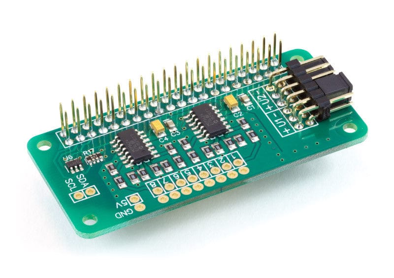
Der ADC Pi Zero ist ein 8-Kanal 17-Bit Analog-Digital-Wandler, der für den Raspberry Pi Zero entwickelt wurde. Der ADC Pi Zero basiert auf zwei Microchip MCP3424 A/D-Wandlern mit jeweils 4 analogen Eingängen. Der MCP3424 ist ein Delta-Sigma-A/D-Wandler mit rauscharmen Differenzeingängen.

Wir haben den ADC Pi Zero so konzipiert, dass er als Single-Ended-A/D-Wandler mit der internen 2,048-V-Referenzspannung arbeitet, wobei die -V-Pins mit Masse verbunden sind. Ein Spannungsteiler auf der ADC Pi Zero Platine bringt den Eingangsspannungsbereich auf einen viel nützlicheren Wert von 0 - 5,06V. In dieser Konfiguration beträgt die Abtastgröße 17 Bit für jeden Kanal.

Einleitung:

Der ADC Pi Zero wird über den GPIO-Port des Raspberry Pi Zero mit Strom versorgt. Erweiterte Pins am GPIO-Anschluss ermöglichen es, den ADC Pi Zero zusammen mit anderen Erweiterungsplatinen zu stapeln.

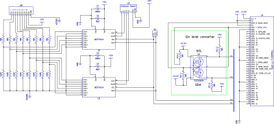
Die beiden MCP3424 A/D-Wandler kommunizieren über i2c mit dem Raspberry Pi, so dass Sie acht analoge Eingänge zur Verfügung haben. Ein Logik-Pegel-Wandler ist auf dem ADC Pi Zero Board enthalten und bietet einen gepufferten 5V i2c Port, der es einfach macht, andere I2C Geräte hinzuzufügen, die mit 5 Volt arbeiten, ohne den 3,3 Volt i2c Port des Raspberry Pi zu beschädigen. Der i2c-Puffer verwendet N-Kanal-Mosfets mit einem maximalen Drainstrom von 100mA.

Die I2C-Adressbits sind über die integrierten Jumper wählbar. Der MCP3424 unterstützt bis zu 8 verschiedene I2C-Adressen, so dass man mit zwei A/D-Wandlern auf jedem ADC Pi Zero bis zu 4 ADC Pi Zero Boards auf einem einzigen Raspberry Pi Zero stapeln kann, was 32 ADC-Eingänge ergibt.

Der MCP3424 enthält eine integrierte 2,048V-Referenzspannung mit einem Eingangsbereich von ±2,048V differentiell (Vollausschlag von 4,096V/PGA). Ein programmierbarer Verstärker bietet dem Benutzer eine wählbare Verstärkung von x1, x2, x4 oder x8, bevor die Analog-Digital-Wandlung stattfindet.

Die Datenrate für die Analog-Digital-Wandlung beträgt 3,75 (17 Bit), 15 (15 Bit), 60 (13 Bit) oder 240 (11 Bit) Samples pro Sekunde. Datenrate und Auflösung können in der Software über die I2C-Schnittstelle konfiguriert werden.

Wir haben einen Artikel in der Wissensdatenbank, ADC-Abtastratenvergleich mit detaillierteren Beispielinformationen und Testskripten zum Vergleich der verschiedenen Bit- und Abtastraten des MCP2424 ADC-Chips.

Nicht verwendete Eingänge sollten mit Masse verbunden werden.

Wenn Sie eine höhere Eingangsspannung abtasten möchten, können Sie unser ADC Pi Eingangsspannungs-Rechner um die zusätzlich benötigten Widerstände und Berechnungswerte zu finden.

Auswahl der I2C-Adresse

Der Analog-Digital-Wandler MCP3424 enthält zwei Adress-Select-Pins, die mit Vss, Vdd verbunden werden können oder potentialfrei bleiben. Dies ergibt 8 mögliche I2C-Adressen für jeden Chip. Der ADC Pi Zero enthält zwei MCP3424 Chips, so dass Sie bis zu 4 ADC Pi Zero Boards auf einem einzigen Raspberry Pi stapeln können. Um die Adressauswahl auf dem ADC Pi Zero zu vereinfachen, haben wir eine Reihe von Adressauswahl-Pins vorgesehen, die mit den mitgelieferten Jumpern konfiguriert werden können. Die Abbildungen unten zeigen die vier empfohlenen Konfigurationen für Ihren ADC Pi Zero und die dazugehörigen I2C-Adressen.

Anmerkung:
Trennen Sie den ADC Pi Zero vom Raspberry Pi, bevor Sie die Adresspins ändern. Möglicherweise müssen Sie die 5V und Masse mit einem Widerstand kurzschließen, um die Kondensatoren zu entladen, damit die neuen Adressen erkannt werden.
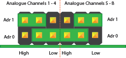
Address selection pins

I 2 C Adresstabelle

Adr 0 Adr 1 I2C-Adresse
Niedrig oder schwimmend Niedrig oder schwimmend 0x68
Niedrig Schwimmer 0x69
Niedrig Hoch 0x6A
Schwimmer Niedrig 0x6B
Hoch Niedrig 0x6C
Hoch Schwimmer 0x6D
Hoch Hoch 0x6E
Schwimmer Hoch 0x6F


Warnung

Verbinden Sie unter keinen Umständen die beiden mittleren Pins miteinander. Dadurch entsteht ein direkter Kurzschluss zwischen den 5V- und den Erdungspins und Ihr Raspberry Pi und ADC Pi Zero Board werden beschädigt oder zerstört.

Empfohlene Adresskonfigurationen

Konfiguration 1:

Analoge Kanäle 1-4 = I2C Adresse: 0x68
Analoge Kanäle 5-8 = I2C Adresse: 0x69
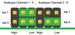
Address Configuration 1

Konfiguration 2:

Analoge Kanäle 1-4 = I2C Adresse: 0x6A
Analoge Kanäle 5-8 = I2C Adresse: 0x6B
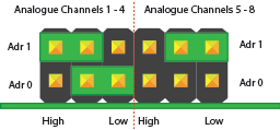
Address Configuration 2

Konfiguration 3:

Analoge Kanäle 1-4 = I2C Adresse: 0x6C
Analogkanäle 5-8 = I2C Adresse: 0x6D
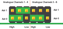
Address Configuration 3

Konfiguration 4:

Analoge Kanäle 1-4 = I2C Adresse: 0x6E
Analogkanäle 5-8 = I2C Adresse: 0x6F
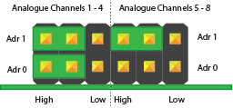
Address Configuration 4

Datenblätter

MCP3424

Kompatibilitäts-Tabelle

Raspberry Pi Model A Nein
Raspberry Pi Model B Nein
Raspberry Pi 1 Model A+ Ja
Raspberry Pi 1 Model B+ Ja
Raspberry Pi 2 Model B Ja
Raspberry Pi 3 Model B Ja
Raspberry Pi Zero Ja
ODroid C1 Ja
ODroid C2 Ja

Eigenschaften

  • 8 x 17-Bit 0 bis 5 V Single-Ended-Eingänge
  • Steuerung über den I2C-Port des Raspberry Pi
  • Stapeln Sie bis zu 4 ADC Pi Zero-Karten auf einem einzigen Raspberry Pi
  • Über Jumper wählbare I2C-Adressen
  • Gepufferter 5V I2C-Anschluss
  • Basierend auf dem MCP3424 von Microchip Technologies Inc.
  • Single-Ended-Vollbereich von 5,0 V
  • On-board 2,048V Referenzspannung (Genauigkeit ± 0,05%, Drift: 15 ppm/°C)
  • On-Board programmierbarer Verstärker (PGA): Verstärkungen von 1, 2, 4 oder 8
  • Programmierbare Datenratenoptionen:
    - 3,75 SPS (17 Bits)
    - 15 SPS (15 Bits)
    - 60 SPS (13 Bits)
    - 240 SPS (11 Bits)
  • Optionen für einmalige oder kontinuierliche Konvertierung

Nicht sicher, welchen ADC Sie benötigen? Prüfen Sie unser Leitfaden für die Umstellung von Analog auf Digital um unsere ADC-Erweiterungskarten zu vergleichen.

Eingangsleistungen & Spezifikationen

Vdd (5V-Pin am I2C-Bus) 5.0V
Alle AD-Eingänge und -Ausgänge VSS-0,4 V bis VDD+0,4 V
Strom an den Eingangspins ±2 mA
I2C SDA/SCL Spannung 5.0 V
Strom am I2C-Anschluss 100 mA


Layout der Karte

Board Layout

Schematische Darstellung

Click to download
Klicken Sie hier, um den Schaltplan als PDF herunterzuladen.

Mechanische Zeichnungen

Mechanical Drawing

Zum Vergrößern Bild anklicken

Beispiel-Code

Wir haben Arduino-, C-, Windows 10 IOT-, Python 2- und Python 3-Bibliotheken für dieses Erweiterungsboard verfügbar. Sie können alle Bibliotheken von github herunterladen:

https://github.com/abelectronicsuk/

Herunterladen der Arduino-Bibliotheken von: https://github.com/abelectronicsuk/ABElectronics_Arduino_Libraries

Zum Herunterladen der C-Bibliotheken auf Ihrem Raspberry Pi in terminal eingeben:

git clone https://github.com/abelectronicsuk/ABElectronics_C_Libraries.git

Zum Herunterladen der Python 2 Bibliotheken auf Ihrem Raspberry Pi in terminal eingeben:

git clone https://github.com/abelectronicsuk/ABElectronics_Python_Libraries.git

Zum Herunterladen der Python 3 Bibliotheken auf Ihrem Raspberry Pi in terminal eingeben:

git clone https://github.com/abelectronicsuk/ABElectronics_Python3_Libraries.git

Herunterladen der Windows 10 IOT-Bibliotheken von: https://github.com/abelectronicsuk/ABElectronics_Win10IOT_Libraries/

Download Python 2 and 3 code samples

Download Arduino code samples

Anleitungen

Wir haben eine Reihe von Tutorials für den ADC Pi, ADC Pi Zero und ADC Pi Plus in unserer Knowledge Base

ADC Pi Zero Tutorials

Montageanleitung

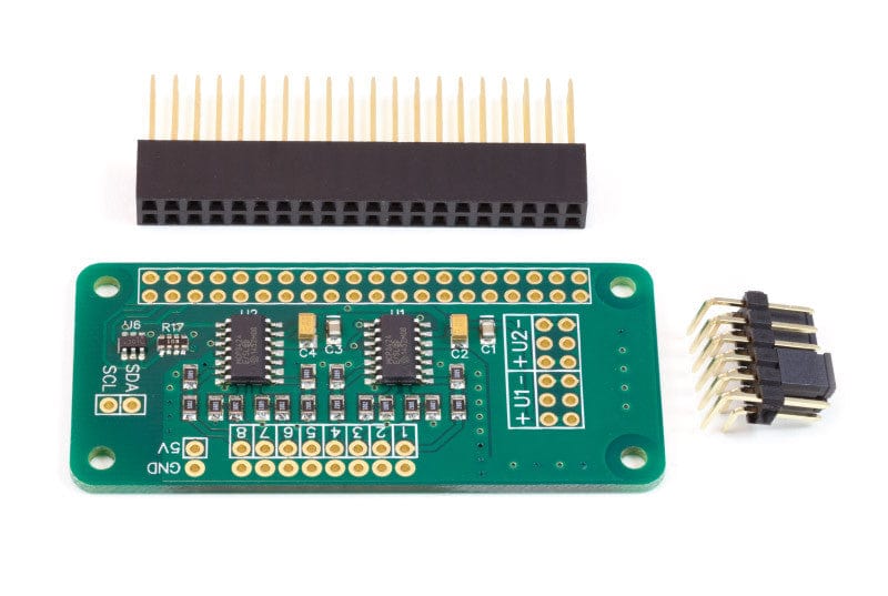
Der ADC Pi Zero wird mit dem 40-poligen GPIO-Anschluss und dem 12-poligen Adressanschluss ohne Lötstellen geliefert. Wir liefern den ADC Pi Zero auf diese Weise, weil der Raspberry Pi Zero auch ohne GPIO-Anschluss geliefert wird und der ADC Pi Zero daher sowohl über als auch unter dem Raspberry Pi Zero angebracht werden könnte.

Bevor Sie den ADC Pi Zero verwenden können, müssen Sie beide Anschlüsse auf die Platine löten. Wir empfehlen, zuerst den 40-poligen GPIO-Anschluss und dann den Adresswahl-Anschluss anzulöten. Wenn Sie den Adresswahlstecker zuerst anlöten, wird es schwierig, an die drei Eckpins des GPIO-Steckers zu gelangen.

PCB Header Montagevorrichtung

Herunterladen und ausdrucken unsere PCB Header Assembly Jig, um Ihre Leiterplatte beim Löten der Header-Pins zu halten.

Use


English Description

The ADC Pi Zero is an 8 channel 17 bit analogue to digital converter designed to work with the Raspberry Pi Zero. The ADC Pi Zero is based on two Microchip MCP3424 A/D converters each containing 4 analogue inputs. The MCP3424 is a delta-sigma A/D converter with low noise differential inputs.

We designed the ADC Pi Zero to work as a single ended A/D converter using the internal 2.048V reference voltage with the -V pins tied to ground. A voltage divider on the ADC Pi Zero board brings the input voltage range to a much more useful 0 – 5.06V. In this configuration the sample size is 17 bits for each channel.

Introduction:

The ADC Pi Zero is powered through the host Raspberry Pi Zero using the GPIO port and extended pins on the GPIO connector allow you to stack the ADC Pi Zero along with other expansion boards.

The two MCP3424 A/D converters communicate via i2c to the host Raspberry Pi giving you eight analogue inputs to use. A logic level converter is included on the ADC Pi Zero board giving you a buffered 5V i2c port making it easy to add other I2C devices which operate at 5 volts without damaging the raspberry pi 3.3 volt i2c port. The i2c buffer uses N-channel mosfets with a maximum drain current of 100mA.

The I2C address bits are selectable using the on-board jumpers. The MCP3424 supports up to 8 different I2C addresses so with two A/D converters on each ADC Pi Zero you can stack up to 4 ADC Pi Zero boards on a single Raspberry Pi Zero giving you 32 ADC inputs.

The MCP3424 contains an on-board 2.048V reference voltage with an input range of ±2.048V differentially (full scale range of 4.096V/PGA). A programmable Gain Amplifier gives the user a selectable gain of x1, x2, x4 or x8 before the analogue to digital conversion takes place.

The data rate for analogue to digital conversions is 3.75 (17 bit), 15 (15 bit), 60 (13 bit) or 240 (11 bit) samples per second. Data rate and resolution can be configured within software using the I2C interface.

We have a knowledge base article, ADC Sample Rate Comparisonwhich has more detailed sample information and test scripts to compare the different MCP2424 ADC chip bit and sample rates.

Unused inputs should be tied to ground.

If you want to sample a higher input voltage you can use our ADC Pi Input Voltage Calculator to find the additional resistors and calculation values needed.

I2C Address Selection

The MCP3424 analogue to digital converter contains two address select pins which can be tied to Vss, Vdd or left floating. This gives 8 possible I2C addresses for each chip. The ADC Pi Zero contains two MCP3424 chips so you can stack up to 4 ADC Pi Zero boards on a single Raspberry Pi. To simplify address selection on the ADC Pi Zero we have included a set of address selection pins which can be configured using the included jumpers. The illustrations below show the four recommended configurations for your ADC Pi Zero and the associated I2C addresses.

Note:
Disconnect the ADC Pi Zero from the Raspberry Pi before changing the address pins. You may need to short the 5V and ground with a resistor to discharge the capacitors in order for the new addresses to be recognised.

Address selection pins

I2C Address Table

Adr 0 Adr 1 I2C Address
Low or Float Low or Float 0x68
Low Float 0x69
Low High 0x6A
Float Low 0x6B
High Low 0x6C
High Float 0x6D
High High 0x6E
Float High 0x6F


Warning

Do not under any circumstanced connect the two centre pins together. This will create a direct short between the 5V and ground pins and will damage or destroy your Raspberry Pi and ADC Pi Zero board.

Recommended Address Configurations

Configuration 1:

Analogue Channels 1-4 = I2C Address: 0x68
Analogue Channels 5-8 = I2C Address: 0x69

Address Configuration 1

Configuration 2:

Analogue Channels 1-4 = I2C Address: 0x6A
Analogue Channels 5-8 = I2C Address: 0x6B

Address Configuration 2

Configuration 3:

Analogue Channels 1-4 = I2C Address: 0x6C
Analogue Channels 5-8 = I2C Address: 0x6D

Address Configuration 3

Configuration 4:

Analogue Channels 1-4 = I2C Address: 0x6E
Analogue Channels 5-8 = I2C Address: 0x6F

Address Configuration 4

Datasheets

MCP3424

Compatibility Chart

Raspberry Pi Model A No
Raspberry Pi Model B No
Raspberry Pi 1 Model A+ Yes
Raspberry Pi 1 Model B+ Yes
Raspberry Pi 2 Model B Yes
Raspberry Pi 3 Model B Yes
Raspberry Pi Zero Yes
ODroid C1 Yes
ODroid C2 Yes

Features

  • 8 x 17-bit 0 to 5V Single Ended Inputs
  • Control via the Raspberry Pi I2C port
  • Stack up to 4 ADC Pi Zero boards on a single Raspberry Pi
  • Jumper selectable I2C addresses
  • Buffered 5V I2C port
  • Based on the MCP3424 from Microchip Technologies Inc
  • Single Ended full-scale range of 5.0V
  • On-board 2.048V reference voltage (Accuracy ± 0.05%, Drift: 15 ppm/°C)
  • On-Board Programmable Gain Amplifier (PGA): Gains of 1, 2, 4 or 8
  • Programmable Data Rate Options:
    - 3.75 SPS (17 bits)
    - 15 SPS (15 bits)
    - 60 SPS (13 bits)
    - 240 SPS (11 bits)
  • One-Shot or Continuous Conversion Options

Not sure which ADC you need ? Check our Analogue to Digital Buyers guide to compare our ADC expansion boards.

Input Ratings & Specifications

Vdd (5V pin on I2C bus) 5.0V
All AD inputs and outputs VSS–0.4V to VDD+0.4 V
Current at Input Pins ±2 mA
I2C SDA/SCL voltage 5.0 V
I2C port current 100 mA


Board Layout

Board Layout

Schematic

Click to download
Click to download schematic PDF.

Mechanical Drawings

Mechanical Drawing

Click image to enlarge

Sample Code

We have Arduino, C, Windows 10 IOT, Python 2 and Python 3 libraries available for this expansion board. You can download all of the libraries from github at:

https://github.com/abelectronicsuk/

Download the Arduino librariesfrom: https://github.com/abelectronicsuk/ABElectronics_Arduino_Libraries

To download the C libraries to your Raspberry Pi type in terminal:

git clone https://github.com/abelectronicsuk/ABElectronics_C_Libraries.git

To download the Python 2 libraries to your Raspberry Pi type in terminal:

git clone https://github.com/abelectronicsuk/ABElectronics_Python_Libraries.git

To download the Python 3 libraries to your Raspberry Pi type in terminal:

git clone https://github.com/abelectronicsuk/ABElectronics_Python3_Libraries.git

Download the Windows 10 IOT libraries from:https://github.com/abelectronicsuk/ABElectronics_Win10IOT_Libraries/

Download Python 2 and 3 code samples

Download Arduino code samples

Tutorials

We have a range of tutorials for the ADC Pi, ADC Pi Zero and ADC Pi Plus in our Knowledge Base

ADC Pi Zero Tutorials

Assembly Instructions

The ADC Pi Zero is supplied with the 40 pin GPIO connector and the 12 pin address connector unsoldered. We supply the ADC Pi Zero this way because the Raspberry Pi Zero is also supplied without a GPIO header and the ADC Pi Zero could therefore be fitted both above or below the Raspberry Pi Zero.

Before using the ADC Pi Zero you will need to solder both connectors onto the PCB. We suggest soldering the 40 pin GPIO connector first and then the address select connector. Soldering the address select connector first will make it difficult to access the three corner pins on the GPIO connector.

PCB Header Assembly Jig

Download and print our PCB Header Assembly Jig to hold your circuit board when soldering the header pins.

Use

Customer Reviews

Be the first to write a review
0%
(0)
0%
(0)
0%
(0)
0%
(0)
0%
(0)

Similar products

Recently viewed